
Archivo:WPPressGaugeDetailHC.jpg
WPPressGaugeDetailHC.jpg (504 × 495 píxeles; tamaño de archivo: 59 kB; tipo MIME: image/jpeg)
Resumen
| Descripción |
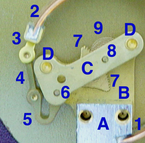
English: Mechanics of a pressure gauge, annotated
Annotated internals of a pressure gauge, contrast enhanced. Mechanical detailsStationary parts:A: Receiver block. This joins the inlet pipe to the fixed end of the Bourdon tube (1) and secures the chassies plate (B). The two holes receive screws that secure the case. B: Chassies Plate. The face card is attached to this on the opposite side. It contains bearing holes for the axles. C: Secondary Chassis Plate. It supports the outer ends of the axles. D: Posts to join and space the two chassis plates. Moving Parts1: Stationary end of Bourdon tube. This communicates with the inlet pipe through the receiver block. 2: Moving end of bourdon tube. This end is sealed. 3: Pivot and pivot pin. 4: Link joining pivot pin to lever (5) with pins to allow joint rotation. 5: Lever. This an extension of the sector gear (7). 6: Sector gear axle pin. 7: Sector gear. 8: Indicator needle axle. This has a spur gear that engages the sector gear (7) and extends through the face to drive the indicator needle. Due to the short distance between the lever arm link boss and the pivot pin and the difference between the effective radius of the sector gear and that of the spur gear, any motion of the bourden tube is greatly amplified. A small motion of the tube results in a large motion of the indicator needle. 9: Hair spring to preload the gear train to reduce gear lash and hysteresis. |
| Fecha |
4 April 2004 |
| Fuente | Transferred from en.wikipedia. |
| Autor | Leonard G. at en.wikipedia |
Licencia
| |
Esta imagen ha sido (por este medio) publicada en el dominio público por su autor, Leonard G. en el proyecto Wikimedia Commons. Esto se aplica mundialmente. En caso de que no sea legalmente posible: |
Registro original de carga
- 2004-04-22 19:25 Leonard G. 504×495× (60279 bytes) Improved contrast annotated pressure gauge image
- 2004-04-22 19:17 Leonard G. 506×495× (70754 bytes) improved contrast image of pressure gauge internals
- 2004-04-04 16:53 Leonard G. 510×495× (53370 bytes) Mechanics of a pressure gauge, annotated
Historial del archivo
Haz clic sobre una fecha y hora para ver el archivo tal como apareció en ese momento.
| Fecha y hora | Miniatura | Dimensiones | Usuario | Comentario | |
|---|---|---|---|---|---|
| actual | 21:52 14 ene 2012 | | 504 × 495 (59 kB) | OgreBot | (BOT): Reverting to most recent version before archival |
| 21:52 14 ene 2012 |  | 504 × 495 (59 kB) | OgreBot | (BOT): Uploading old version of file from en.wikipedia; originally uploaded on 2004-04-22 19:25:22 by Leonard G. | |
| 18:11 3 sep 2005 |  | 504 × 495 (59 kB) | Saperaud~commonswiki | Annotated internals of a pressure gauge, contrast enhanced. ==Mechanical details== ===Stationary parts:=== '''A:''' Receiver block. This joins the inlet pipe to the fixed end of the Bourdon tube (1) and secures the chassies plate (B). The two holes rec |
Usos del archivo
La siguiente página usa este archivo:
Uso global del archivo
Las wikis siguientes utilizan este archivo:
- Uso en ca.wikipedia.org
- Uso en cs.wikipedia.org
- Uso en de.wikipedia.org
- Uso en en.wikipedia.org
- Uso en fr.wikipedia.org
- Uso en hr.wikipedia.org
- Uso en ja.wikipedia.org
- Uso en vi.wikipedia.org